So you want to make a badge? Badge Creation 101
Jeff Geisperger (Security Engineer)
DEF CON 33 · Day 1 · Main Stage
Overview
Jeff Geisperger, also known as Big Taro, delivered an insightful and highly practical talk at DEF CON titled "So you want to make a badge? Badge Creation 101." Geisperger, a security engineer by day and a prolific hardware badge creator by night, shared his expertise in transforming a nascent interest in custom hardware into tangible, blinking, and often interactive electronic badges. The presentation served as a foundational guide for aspiring badge makers, demystifying the entire process from conceptualizing a simple add-on (SAO) to designing a full-fledged conference badge.
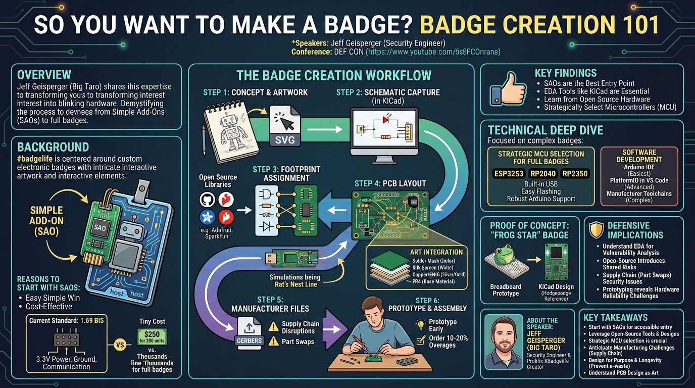
Key moments
- 0:00 Introduction to Badge Creation 101 and #badgelife
- 2:00 Understanding SAOs: Simple Add-Ons for more bling
- 3:00 Why start with SAOs? Easy entry into hardware
- 4:00 SAO standard: Pinout, power, and physical connectors
- 5:20 First SAO circuit: A simple always-on LED
- 5:50 Introducing EDA software for circuit board design
So you want to make a badge? Badge Creation 101
Speakers: Jeff Geisperger (Security Engineer)
Conference: DEF CON
YouTube: https://www.youtube.com/watch?v=e6dmGupBsJk
Overview
Jeff Geisperger, also known as Big Taro, delivered an insightful and highly practical talk at DEF CON titled "So you want to make a badge? Badge Creation 101." Geisperger, a security engineer by day and a prolific hardware badge creator by night, shared his expertise in transforming a nascent interest in custom hardware into tangible, blinking, and often interactive electronic badges. The presentation served as a foundational guide for aspiring badge makers, demystifying the entire process from conceptualizing a simple add-on (SAO) to designing a full-fledged conference badge.
The talk addresses a common barrier to entry in the vibrant "badge life" community: the perceived complexity of electronics design and manufacturing. Geisperger's goal was to provide a "near zero knowledge" pathway for enthusiasts to get started, emphasizing enjoyment and learning over immediate optimization or professional-grade engineering. He meticulously walked attendees through the essential tools, standards, and workflows, demonstrating that creating custom hardware is an achievable endeavor for anyone willing to invest time and effort.
This presentation is particularly significant for the DEF CON community and the broader hardware hacking scene. It not only encourages participation in the #badgelife phenomenon but also equips individuals with the fundamental skills to understand, design, and even troubleshoot custom electronic devices. For security professionals, a deeper understanding of hardware creation can foster appreciation for supply chain vulnerabilities, component integrity, and the challenges in securing physical systems, making this talk a valuable resource for both hobbyists and those with a professional interest in device security.
Background
▶ Watch: Introduction to Badge Creation 101 and #badgelife (0:00)
The "badge life" phenomenon at conferences like DEF CON is a subculture centered around custom-designed electronic badges, often featuring intricate artwork, interactive elements, and hidden challenges. These badges serve as both a form of artistic expression and a canvas for hardware hacking. A common entry point into this world is the creation of a Simple Add-On (SAO). Originally dubbed "Shitty Add-On" before a more PC rebrand, SAOs are small, auxiliary PCBs designed to attach to a host conference badge, typically via a standardized six-pin connector. They enhance the host badge with additional "bling," functionality, or aesthetic flair.
Geisperger advocates starting with SAOs for several compelling reasons. Firstly, they offer an easy, simple win, providing immediate gratification and a tangible product without the overwhelming complexity of a full badge. This allows newcomers to gauge their interest and enjoyment in the hardware creation process before committing to larger projects. Secondly, SAOs are significantly more cost-effective to produce. A run of 200 SAOs might cost around $250, whereas a complex full badge run could easily run into thousands or even tens of thousands of dollars. This lower financial barrier makes experimentation more accessible.
The current SAO standard, 1.69 BIS, is a community-driven specification for fun. It operates on a 3.3-volt standard and typically draws around 280 milliamps. The pinout consists of six pins, where four are intended for communication with the host badge, and two (power and ground) are sufficient for simple add-ons. Geisperger highlights the evolution of the standard, noting that earlier four-pin versions often led to SAOs falling off, necessitating the adoption of more secure shrouded key connectors in the 1.69 BIS standard. This foundational understanding of SAOs and their benefits forms the bedrock for transitioning into more complex badge designs.
Key Findings
▶ Watch: Why start with SAOs? Easy entry into hardware (3:00)
Geisperger's talk systematically breaks down the badge creation process into actionable steps, emphasizing a learn-by-doing approach. The key findings and contributions can be summarized as follows:
- SAOs as the Entry Point: The most crucial finding is the recommendation of SAOs as the ideal starting point for anyone interested in custom hardware. Their simplicity, low cost, and quick turnaround provide an accessible and rewarding introduction to electronics design, allowing creators to build confidence and assess their interest before tackling more ambitious projects.
- Leveraging Electronic Design Automation (EDA) Tools: The talk underscores the indispensable role of EDA software in translating electrical circuits into physical circuit boards. Geisperger highlights KiCad as a free and capable tool for hobbyists, while also mentioning alternatives like EasyEDA (integrated with JLCPCB), Autodesk Eagle, and the professional-grade Altium Designer. The core process involves creating a schematic, assigning footprints (the physical layout for components), laying out the PCB, and exporting manufacturing files.
- Open Source as a Learning Accelerator: A significant takeaway is the power of open-source hardware and software. Geisperger strongly recommends learning from experts like Adafruit and SparkFun, who openly publish their schematics and design files for development boards. This allows new designers to "hodgepodge" existing, proven circuits into their designs, avoiding the need to reinvent fundamental components like power management or display drivers. This approach dramatically reduces the learning curve and time investment.
- Strategic Microcontroller Unit (MCU) Selection: For full badges, the choice of MCU is critical. Geisperger recommends chips like the ESP32S3, RP2040, or RP2350 due to their built-in USB (simplifying flashing and connectivity), ease of flashing (especially the RP2040/2350's drag-and-drop firmware capability), and robust Arduino library support. These features significantly streamline the development process for hobbyists.
- Addressing Real-World Manufacturing Challenges: Beyond the design, Geisperger provides practical advice on manufacturing. He highlights common issues such as supply chain disruptions, last-minute part swaps, data sheet misrepresentations, and the often-underestimated manual labor cost for assembly (e.g., attaching 1,000 screens). To mitigate these, he strongly advises prototyping early and often and planning for overages (e.g., ordering 10-20% more parts than needed) to account for failures.
- Designing for "Badge Life" Longevity and Fun: Finally, Geisperger emphasizes the importance of designing badges with purpose beyond mere blinking. He advocates for CTF challenges, awesome bling and light patterns, and preventing e-waste by incorporating features that give the badge utility after the conference (e.g., turning it into a dev board, a TV-B-Gone, or a game). This ethos encourages thoughtful design and extends the life and enjoyment of the created hardware.
Technical Deep Dive
▶ Watch: SAO standard: Pinout, power, and physical connectors (4:00)
The technical journey of badge creation, as outlined by Geisperger, begins with an understanding of Electronic Design Automation (EDA) software. For hobbyists, KiCad is the recommended free and open-source tool, offering a comprehensive suite for schematic capture and PCB layout. The process starts by creating a new project and building a schematic, which is a logical representation of the electronic circuit. For simple SAOs, this might involve just a resistor, an LED, and the SAO connector. Custom parts, like the SAO connector itself, can often be downloaded from open-source repositories (e.g., Twinkle's parts library), providing the schematic symbol, footprint, and 3D model.
Once the schematic is complete, the next critical step is assigning footprints. A footprint defines the physical pads and holes on the PCB that a component will solder onto. While standard components like LEDs, resistors, and capacitors often adhere to standard sizes (e.g., 0603 or larger for easier rework), it's crucial to verify availability and correct footprints from suppliers like JLCPCB. Tools like "Easy EDA to KiCad" can streamline this by pulling part numbers and associated files directly into KiCad. Geisperger warns that manufacturer-provided footprints can sometimes be inaccurate, underscoring the importance of prototyping.
With footprints assigned, the design moves to the PCB editor. Here, the components are physically placed on the board, and traces (electrical connections) are routed based on the connections defined in the schematic. KiCad's visual cues, like "rat's nest" blue lines, guide the user in making these connections. Beyond electrical functionality, art integration is a hallmark of badge life. Vector art (e.g., SVG format) is imported into KiCad and broken down into different PCB layers:
- Solder mask: Defines the primary color of the board (red, green, blue, black, white, yellow, purple).
- Silk screen: Used for white or black legends, logos, and finer details.
- Metal (copper/ENIG): Appears silver or gold, typically for exposed pads or decorative elements.
- FR4: The base material, a semi-transparent yellowish color, visible in transparent areas where no solder mask is applied.
Artwork is outlined to create the board's edge cuts (its physical shape) and then broken into these layers. Filled zones are used to flood areas with copper, creating large ground planes or decorative metallic surfaces. Aesthetic positioning of components within the artwork is crucial for the final visual appeal.
For full-fledged badges, the technical depth increases. Geisperger advises selecting a suitable MCU, recommending the ESP32S3, RP2040, or RP2350. These chips are favored for their integrated USB (eliminating the need for external serial-to-USB converters), straightforward flashing mechanisms (especially the RP2040/2350's drag-and-drop firmware), and excellent Arduino library support. The Raspberry Pi Foundation provides open-source reference designs for the RP2350 in KiCad, offering a fully functional starting point for the MCU's core circuitry (MCU, flash, USB). This allows designers to focus on integrating peripherals rather than designing the complex MCU subsystem from scratch.
Software development for badges typically involves one of three approaches:
- Arduino IDE: Easiest for beginners, offering quick setup and extensive libraries for common components like Adafruit Neopixel (for WS2812B LEDs), Adafruit Graphics, TFTSPI, and Love Yan Graphics (for screens), and EasyButton or ButtonFever (for input). Its limitations include slower compile times and less optimization.
- PlatformIO in VS Code: More robust for advanced projects, allowing integration of Arduino libraries with raw code. While setup can be challenging, it provides a mature toolchain for complex firmware.
- Manufacturer-supplied toolchains: For highly specialized or exotic chips, requiring manual setup and compilation, not recommended for beginners.
The transition from a breadboard prototype to a final PCB involves translating the interconnected development boards and wires into a single, cohesive KiCad schematic and layout. By leveraging open-source schematics from reputable vendors, designers can incorporate complex peripheral circuits (e.g., display breakouts, audio circuits) directly into their custom board, reducing the need for multiple add-on modules and creating a more integrated, compact design. This iterative process of prototyping, schematic capture, layout, and art integration, heavily supported by open-source resources, forms the technical backbone of modern badge creation.
Demo / Proof of Concept
▶ Watch: First SAO circuit: A simple always-on LED (5:20)
While Geisperger's talk was a conceptual and instructional guide rather than a live coding or hardware demonstration, he effectively "demonstrated" the entire badge creation workflow through a series of visual examples and a step-by-step walkthrough in KiCad.
The initial proof of concept centered on creating a simple SAO:
- Conceptual Circuit: The talk began by illustrating the most basic circuit: an LED, a resistor, and a power source (represented by the SAO connector).
- KiCad Schematic: Geisperger showed how this simple circuit is translated into a KiCad schematic, placing symbols for the LED, resistor, and SAO connector, then connecting them with wires. He highlighted the ease of importing custom SAO symbols and footprints from open-source repositories.
- Footprint Assignment: Visual examples demonstrated how generic schematic symbols are linked to specific physical footprints (e.g., 0603 size for the LED/resistor, the specific SAO connector footprint).
- PCB Layout: The parts were then placed on the virtual PCB, and KiCad's "rat's nest" lines guided the routing of traces to complete the electrical connections.
- Art Integration: The "demo" then extended to importing vector art (a hacker dude on a laptop) into KiCad. Geisperger showed how the art is broken into layers (solder mask, silk screen, copper, FR4) and integrated with the circuit, placing the LED as the hacker's "eyes" and the SAO connector at the bottom. The board's custom shape was defined using the edge cuts layer.
- 3D Viewer: The final SAO design was presented in KiCad's 3D viewer, illustrating the completed physical product with its custom shape, artwork, and components.
Beyond the SAO, Geisperger demonstrated the scalability of this process to full badges. He showcased a breadboard prototype of a complex badge, highlighting how various development boards and components are initially wired together. He then presented the corresponding intricate KiCad schematic for that breadboard setup. The transition from prototype to final product was vividly illustrated using his own "Frog Star" badge, showing the RP2350 reference design (an open-source foundation) side-by-side with his customized design. This visual comparison effectively proved that complex badges can be built by "hodgepodging" proven open-source circuits and then refining them into a unique aesthetic. The talk concluded by showing the final "Frog Star" badge, demonstrating the successful application of all the discussed principles from simple concept to a functional, aesthetically pleasing, and interactive device.
Defensive Implications
▶ Watch: Introducing EDA software for circuit board design (5:50)
While Jeff Geisperger's talk focuses on the creation of hardware badges for fun and learning, the insights shared have significant, albeit indirect, defensive implications for security professionals. Understanding the entire lifecycle of custom hardware, from design to manufacturing and assembly, provides a crucial perspective on potential vulnerabilities and points of compromise.
Firstly, the discussion of EDA tools like KiCad and the process of schematic capture and PCB layout is fundamental. Defenders who understand how circuits are designed can better analyze hardware for security flaws, such as exposed debug ports, insecure communication interfaces, or inadequate power filtering that could lead to side-channel attacks. Knowing how footprints are assigned and how components are laid out can help in identifying potential tampering or unauthorized modifications to a device's hardware.
Secondly, the reliance on open-source hardware and software libraries (e.g., Adafruit schematics, Arduino libraries) presents a double-edged sword. While it accelerates development and learning, it also introduces shared vulnerabilities. A flaw in a widely used open-source library or reference design could propagate across numerous custom hardware projects. Defenders need to be aware of the provenance of components and libraries used in custom devices, as a compromised upstream dependency could lead to exploitable weaknesses in the final product.
Thirdly, Geisperger's emphasis on supply chain issues directly highlights a critical area of concern for hardware security. Problems like last-minute part swaps, data sheet misrepresentations, and the sheer complexity of sourcing components can introduce subtle but significant security risks. A seemingly benign part swap could introduce a component with different electrical characteristics, undocumented features, or even malicious firmware. Defenders involved in hardware procurement or auditing need to implement rigorous verification processes, including vetting suppliers, performing component authentication, and conducting functional testing to detect such compromises.
Finally, the talk's practical advice on prototyping and accounting for part failures underlines the inherent challenges in hardware reliability. While Geisperger frames this in terms of ensuring functional badges, for security, it translates to the importance of robust quality control and testing. A "bad button" or "bad USB" in a badge might be a minor inconvenience, but in a critical security device, it could represent a single point of failure or an entry vector for attacks. Understanding the failure rates and the need for overages can inform strategies for building redundancy and resilience into secure hardware designs.
In essence, while "Badge Creation 101" is not a defensive security talk, it equips security professionals with a deeper understanding of the hardware builder's mindset, tools, and challenges. This knowledge is invaluable for threat modeling custom devices, identifying supply chain risks, and developing more effective hardware security strategies.
Key Takeaways
- Start with SAOs for Accessible Hardware Creation: Simple Add-Ons (SAOs) are an ideal, low-cost (around $250 for 200 units), and manageable entry point into custom hardware design, allowing beginners to gain confidence and enjoyment without significant financial or time commitment.
- Leverage Open-Source Tools and Designs: Free EDA software like KiCad is powerful for schematic capture and PCB layout. Accelerate learning and development by "hodgepodging" proven open-source schematics and libraries from experts like Adafruit and SparkFun, which significantly reduces design complexity.
- Strategic MCU Selection is Crucial: For full badges, choose MCUs like the ESP32S3, RP2040, or RP2350 due to their built-in USB, easy flashing mechanisms (especially drag-and-drop for RP2040/2350), and robust Arduino library support, simplifying firmware development.
- Anticipate and Mitigate Manufacturing Challenges: Be prepared for real-world issues like supply chain disruptions, last-minute part swaps, and inaccurate data sheets. Always prototype early and often and plan for 10-20% overages on parts to account for manufacturing defects and component failures.
- Design for Purpose and Longevity: Beyond blinking lights, strive to incorporate CTF challenges and practical utility into badges to prevent e-waste. Features like making the badge a dev board, a TV-B-Gone, or an interactive game enhance its value and lifespan.
- Understand the Art of PCB Design: PCB design involves more than just electronics; it's also an art form. Utilize vector art and break it into distinct PCB layers (solder mask, silk screen, copper, FR4) to achieve desired visual effects and custom board shapes.
About the Speaker(s)
Jeff Geisperger, who also goes by the handle Big Taro, is a security engineer with approximately 15 years of experience in the devices sector. In his professional role, he "hacks stuff" as a security engineer, indicating a deep technical background in offensive and defensive security practices related to hardware. Outside of his 9-to-5, Geisperger is a passionate and prolific contributor to the #badgelife community, having dedicated about four years to "making Blinky hardware." At the time of this talk, he had released four and a half badges at DEF CON, including the Fight Dystopia party badge, the Gunslinger Begun and Sheriff SAO, a submarine badge, and the Frog Star badge. His dedication to badge creation is evident in his humorous self-description of his intense work schedule, underscoring his deep commitment and expertise in custom hardware design and manufacturing.
Reviews
Dr. Zero (Offensive Security Researcher) — SOLID
Competent, honest, community-facing intro talk that does exactly what it sets out to do: lower the barrier to entry for badge creation at DEF CON. No novel research, no security revelations, but it's not pretending to be that — it's a well-structured 101 session for a real audience gap.
Heather Calloway (CISO) — PASS
A competent hobbyist tutorial on PCB design and badge culture at DEF CON. Outside my lane entirely — no governance angle, no institutional risk, no defender decision path. Routing to zero.